large

Improvement of installation and dismantling of submersible pump units in the conditions of underground leach mines

O. M. Kurbonov*

Department of Mining, Navoi State Mining Institute, Navoiy, Uzbekistan

Address for correspondence: O. M. Kurbonov, Navoi State Mining Institute, P.M.B. 210100, M. Torobiy Street 129-House, 29-Apartment, Navoiy, Uzbekistan, E-mail: agent7001.oq@gmail.com
Submitted: 17-11-2020, Accepted: 28-11-2020, Published: 30-12-2020

ABSTRACT

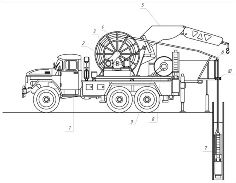
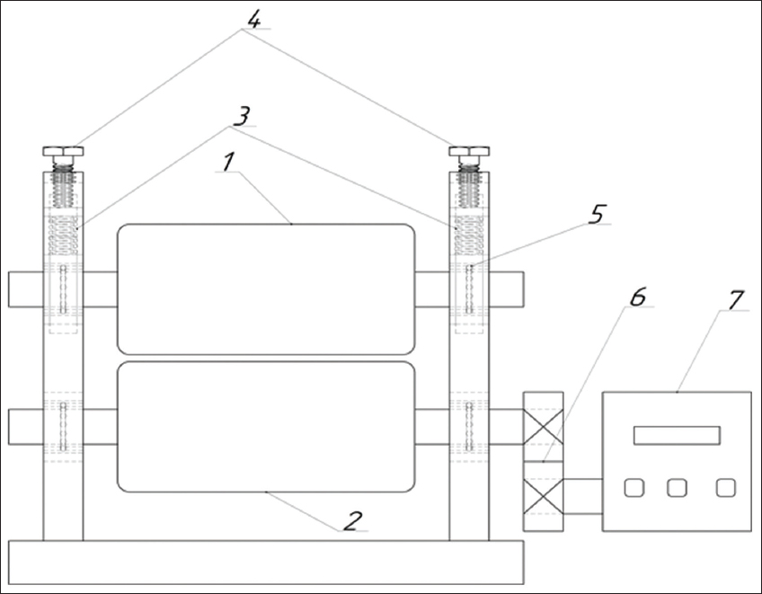
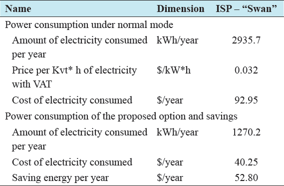
Uranium mining by underground leaching method is currently the newest and most progressive method. When mining uranium using this method, there is no need to build expensive mines or open pits and use many materials, and the number of people working in the construction and operation of deposits is reduced. It is possible to develop deposits with poor metal content. Further, expansion of underground leaching will be accompanied by improvement of technical means and technological processes. Improvement of machines, plants, and production processes is now one of the most important directions of technical progress in the field of underground leaching. Improvements and introduction of new technical solutions increase the reliability of the pumping station and units, the safety of its equipment, and provide the most economical work of the pump units and the station as a whole, as well as the study of the technology of installation and dismantling of pumps in pumped wells by installation of submersible pumps (ISP) – “Swan” is an actual scientific and practical task. The article deals with the issues of improving installation and dismantling of submersible pump units in the conditions of underground leaching mines. The results of performed analysis of different methods and devices for the purpose of tool tracking in wellbore, depending on axial depth and determination of pumping equipment installation length within specified depth limits in technological well of underground leaching ore are covered.The description, design elements, operating principle, technical and economic indicators of the developed technical solution and principal design scheme of the device for optimization of the process of mounting and dismounting pumps in wells ICP(Installation of submersible pumps) - Swan-type unit are presented.

Keywords: Cable, depth meter, installation length, method, mine, mounting installation, mounting-dismounting of pump unit, odometer, submersible pump, technological well, underground leaching

INTRODUCTION

Efficiency of uranium deposits development by underground leaching depends on precise installation of pumping equipment in the technological well within specified depth limits, which are determined by hydrostatic and hydrodynamic pressure parameters in the well.

To solve this problem, before putting the complex of pumping equipment and flexible pipelines into the well, a full length pipeline is laid on the surface of the well and their length is measured. This is a rather time-consuming process and the precise depth of the pumping equipment installation is not always ensured at the well depth.

Our proposed device of mechanical depth meter of submersible pump column installation allows improving accuracy of depth measurement and control of downhole pumping equipment at an accurate depth during well operations.

Purpose of the Work

In this work, we considered the method of improving the installation of submersible pumps (ISP) – “Swan,” which is used for installation and dismantling of submersible pump units in the development of mines by underground leaching.

Discussion of the Issue

Efficiency and low production costs of uranium deposits development by underground leaching method are provided by precise installation of pumping equipment in the technological well within specified depth limits, which are determined by hydrostatic and hydrodynamic pressure parameters in the well and are an actual scientific and practical task.

In practice, to solve this problem, various methods and devices are used to track the tool in the wellbore, depending on the axial depth and determine the length of the pumping equipment installation within the specified depth limits in the technological well of underground leaching of ore.[1]

The most common method and device is mechanical cable length meters, when the source of the signal is mechanical movement.[2-5] The stroke counter counts the reciprocating movements of the lever, the length counter uses a measuring wheel, the speed counter is paired with the drive. Length meters of mechanical type can be contact and non-contact.[6]

Contact meters determine the length by mechanical contact between the measuring device and the material being measured.

Non-contact laser or electron optical length meters are high-tech devices with the most precise classes and have a limited distribution in cable measurements because of the high cost of work.

Wheel length meters with electronic pulse counter are the most common and promising class of devices that include both mechanical and electronic components. Many types of these meters are able not only to record the length of the unwinding cable but also to manage the motors responsible for unwinding the coil with the cable.[7]

To solve the problem, before the complex of pumping equipment and flexible pipelines is put into the well, a full length pipeline is laid on the surface of the well and their length is measured with a mechanical counter. Mechanical length meter consists of a measuring device, which is mounted on a frame with a device for passing the measured material. In such counters, the meter is a measuring wheel, which rolls on the cable to be measured and determines its length.

Depending on the type of device, the meter may be of mechanical or electronic-mechanical design. A mechanical length meter is a device that converts measurement data into a certain length value by means of a conversion factor. The electronic-mechanical meter has sensors that respond to marks on the end of the wheel. When measuring, the signal from these marks is fed to the electronic unit, which converts the information and displays it in the usual form on the scoreboard. This is a rather time-consuming process and the exact depth of the pumping equipment installation is not always provided by the well depth.[8]

MATERIALS AND METHODS

As a result of the research, the technical solution and principal design scheme of the device were developed to optimize installation and dismantling of pumps in pumping wells by ISP – “Swan” type units. At the same time, the developed device can be referred to the devices for determining the length of pumping equipment installation within the specified depth limits in the technological well of underground leaching of ore. The analogs of the developed method are the methods based on tracking the tool in the wellbore depending on the axial depth, which is the distance from the surface (wellhead) along the well axis to the tool location. The disadvantage of these devices is the high labor intensity, associated with the introduction of additional equipment in the design of lifting units, which requires qualified maintenance, low measurement accuracy.

In this case, the string of pipes connected to each other, run into the well with a rope winch, equipped with a weight gauge on the traveling block, and determined the idle runs of the traveling block on the readings of the weight gauge. In this case, the movement of the column in time and space recorded by a video camera on the movement of the target attached to the hoist rope winch block.[9]

However, this method is characterized by the use of expensive control devices with the ability to simultaneously view the upper and lower position of the target while moving the column, the target is placed, in turn, in the lower and upper positions, and this is a rather laborious process.

Technical Solution for Optimization of Installation and Disassembly Works of Pumps in Pumping Wells by ISP – “Swan” Type Units

The Swan device is used for well construction and installation of submersible pumping equipment at a certain well depth and mounted on the chassis of ZIL-131 vehicles used in technology for the development of uranium deposits by underground leaching. The depth gauge is used to determine the depth of pumping equipment location in the technological well of underground leaching of ore. The depth gauge enables to improve accuracy of depth measurement and control of downhole pumping equipment at precise depth during well operations.[10]

The task of the device is to expand the functional capabilities of the units (Swan) using a special device for passing polyethylene pipelines and cables through the gap between two cylindrical rollers, allowing accurate determination of their length, as well as the place of installation of pumping equipment by well depth.

The device for depth measurement of the submersible pump column installation consists of a base, two cylindrical rollers rotating around its axis (one of them is fixed and the other can be changed in the plane perpendicular to the length of the pipeline) and fixed to the fixed roller through the coupling of the odometer device. The technical result is improved accuracy of depth measurement and control of downhole pumping equipment at precise depth during downhole operations.

This device allows you to expand the functionality of the device for determining the length of the installation of pumping equipment within the specified depth limits in the technological well by changing the gap for passing polyethylene flexible pipelines of different diameters in the process of launching the string of pumping equipment.

The efficiency of the depth gauge is achieved by passing polyethylene pipelines and cables through the gap between the two cylindrical rollers and the production of odometer measurements, allowing accurate determination of their length, as well as the place of installation of pumping equipment by well depth.

Figure 1 shows the structural scheme of “Swan” installation for launching and lifting of the casing pumps during construction and repair of geotechnological wells, in which the device is installed to measure the length of polishing pipelines and cables to determine the exact location of the pumping equipment.

thumblarge

Figure :1 The constructive scheme of installation of the installation of submersible pumps type – “Swan.” (1) Chassis of ZIL-131 car; (2) hose polyethylene; (3) reducer; (4) electric motor of hose reel; (5) hydraulic crane; (6) direction polyethylene hose; (7) submersible pump unit; (8) drum of electric cable; (9) electric motor of cable reel; (10) mechanical depth meter of submersible pump column installation

A distinctive feature of the device is that the installation itself “Swan” will be loosened mechanical depth gauge of the submersible pump column installation, which is shown in element 10 in Figure 1, the circuit diagram which is shown in Figure 2.

thumblarge

Figure :2 Principal scheme of the device for depth measurement of submersible pumps installation

In the submersible pump installation, depth gauges provide for the process of mounting the submersible pump unit hose pipes, and the cable passes through the gap between the movable 1 and fixed 2 rollers. Adjustment of the gap is carried out with the help of pressure spring 3 and fixer 4 controls the thickness and diameter of the measured hose. Rotation transmission of the fixed roller, whose axis has a rigid connection with the bearing unit 5 and through the clutch 6 is carried out to the odometer 7, the reading of which allows you to determine the exact depth of installation of pumping equipment.

RESULTS AND DISCUSSION

Mechanical depth gauge of submersible pump column installation allows improving accuracy of depth measurement and control of downhole pumping equipment at precise depth during well operations.

Feasibility study of the developed device and recommendations for improvement of installation and dismantling works of submersible pump units in the conditions of underground leaching mines is performed by calculation of electric power consumption which is presented below.

Calculation of electricity consumption per shift and per year during installation and dismantling of submersible pump units according to the proposed option is determined by the following formula:

Wcycle = Pr EUR t=7.693 0.85 0.09 = 0.58 kWh

where: EUR = 0.85 equipment usage rate overtime;

t= 0.09 h (5.5 min) duration of the calculation period of soaking the hose on the drum of the installation at one cycle of installation and disassembly work;

Pr – rated power of the hose reel motor installed in the ISP – “Swan” unit, which is determined by the following expression:

thumblarge

where: Ip = 14 A phase current determined on the basis of theoretical and experimental analyses.

On the average, one unit of ISP – “Swan” type performs 6 cycles of assembly and disassembly work per day. Then, the calculation of electricity consumption is determined as follows:

Wperday = Wcycle H = 0.58 6 = 3.48 kWh/day

where: H –average number of installation and dismantling works in one ISP – “Swan” installation in 1 day.

The annual power consumption for installation and dismantling of one unit of ISP – “Swan” type is determined by the following expression:

Wyear = Wperday Y = 3.48 365 = 1270.2 kWh/year

Results of economic efficiency calculation of the proposed device for installation and dismantling of submersible pump units are given below.

Capital expenditures: Purchase of the proposed unit – USD 33.88; commissioning (17%) – USD 5.74; equipment delivery (10%) – USD 3.38, thus total capital expenditures are USD 42.91.

Table 1 shows the power consumption by variants of the conventional ISP – Swan equipment and when we apply the proposed depth gauge.

Table :1 Costs of electricity by option

thumblarge

Researches have established that the annual power consumption for installation and dismantling of submersible pump units by the existing method in a normal mode with installations of type ISP – “Swan” is on the average 2935 kW*h/year.

On Figure 3, there is a calculated forecast of power consumption of the basic configuration of the ISP – “Swan” and our proposed configuration with a device for measuring depth by years of operation.

thumblarge

Figure :3 Changes in power consumption at different configuration of the installation of submersible pumps – “Swan.” (1) Basic configuration, (2) with the device for depth measurement

At implementation of the developed technical solution of optimization of installation and dismantling works of pumps in pumping wells by ISP – “Swan” type units, energy saving for one unit is as follows:

W = W1W2=2935.7–1270.2=1665.5 kWh/year.

From the results of the economic efficiency assessment, it is observed that the use of the device for depth measurement allows to reduce the cost of electric energy by 57%, which, in turn, contributes to the reduction of the cost of operation of this unit.

CONCLUSION

The research carried out allowed us to draw the following main conclusions, which have important scientific and practical implications:

  • Efficiency of uranium deposits development by underground leaching depends on the precise installation of pumping equipment in the technological well within the specified depth limits, which is determined by the parameters of hydrostatic and hydrodynamic pressures of the well

  • To achieve such a task, a full length pipeline is laid on the surface of the well and its length is measured before the complex of pumping equipment and flexible pipelines is launched into the well. This is a rather time-consuming process and the precise depth of pumping equipment installation is not always ensured

  • The offered device of mechanical depth gauge of submersible pump column installation allows increasing accuracy of depth measurement and control of downhole pumping equipment at precise depth during well operations

  • Use of the recommended equipment helps to save more than 57% of electricity per year during installation and dismantling of submersible pump units

  • Installation of the proposed device on ISP – “Swan” type units in addition to the economic efficiency of electricity additionally reduces the time of preparatory work for installation or dismantling of submersible pump units.

REFERENCES

1.  Lobachev PB. Pumps and Pumping Stations. Moscow:Stroizdat;2000.

2.  Bystritsky GF, editor. Power Equipment of Industrial Enterprises. 2nd ed. Moscow:Academia Publishing Center;2005. 304.

3.  Gerasimov VG, editor. Electrotechnical Handbook. 9th ed. Moscow:MPEI Publishing House;2004. 4.

4.  Kozhevnikov NN, editor. Economics in Energy:A Textbook. Moscow:Academia Publishing Center;2003. 384.

5.  Mahmudov AM, Khudaiberdiev SM. Determination of basic parameters of energy efficiency of pump units operation in the technology of underground leaching scientific. Technical Prod J Mountain Newsletter Uzbekistan Navoiy 2012;50:73-5.

6.  Petrovykh LV, Marchenko AY, Ivashchenko EP, Marchenko M, Saltanov SN, Barinov IM, et al. Determination of the necessary depth of regulation of drainage systems in conditions of overestimated pump head. Izvestia Ural State Mining Univ 2015;4:62-6.

7.  Gyngazova GS, Milyaev DV, Yermoshin NI. Development of the length meter of non-magnetic extended products by vortex-current method. Bull Sci Siberia 2013;1:117-28.

8.  Stefanovich BJ. Vasilyevich PV. Application of the device length meter in forest engineering Scientific. Tech Prod J Actual Prob Forest Complex 2004;1:61-9.

9.  Method and Devices for Measuring Length and Speed of Tubing Column Movement during Lowering and Lifting Operations (Russian Federation Patent No. 2324812 MPK E21B 44/00, 19/00). Registration Date:10.08.2016. Federation Patent;2016.

10.  Devices of Autonomous Depth Control for Downhole Equipment. (Patent of Russian Federation No. 2461708 MCP E21B47/04 G01B21/18). Date of Registration 20.09.2012;Russian Federation;2012.