large

A comparative analysis on the performance of universal motor when driven by alternating current/direct current

I. A. Araga1*, A. E. Airoboman1, A. P. Inalegwu2, I. A. Afolayan1, F. O. Adunola1

1Department of Electrical/Electronic Engineering, Nigerian Defence Academy Kaduna, Nigeria, 2Energy Commission of Nigeria, Nigeria

Address for correspondence: I. A. Araga, Department of Electrical Electronics Engineering, Nigeria Defence Academy, Kaduna, Nigeria. E-mail: aaidris@nda.edu.ng
Submitted: 15-09-2020, Accepted: 24-10-2020, Published: 30-12-2020

ABSTRACT

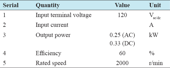
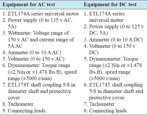
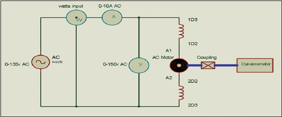
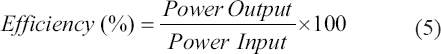
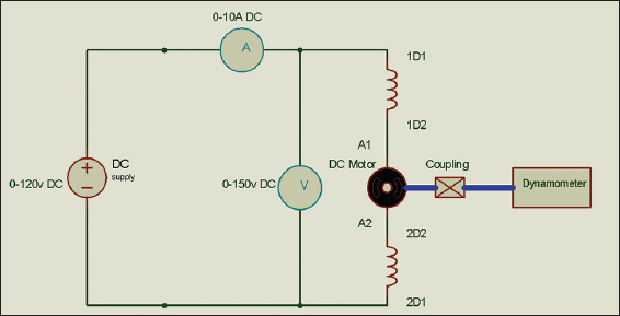
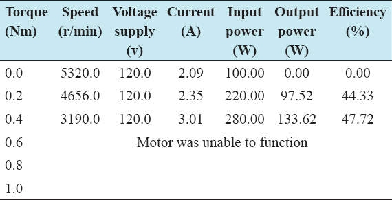
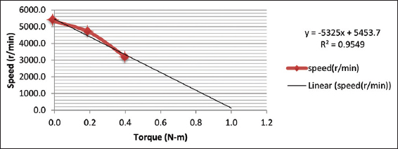
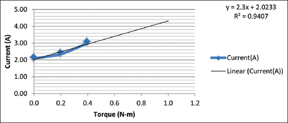
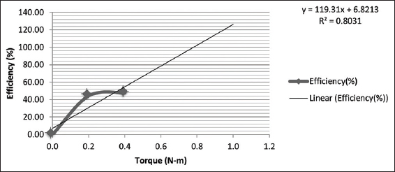
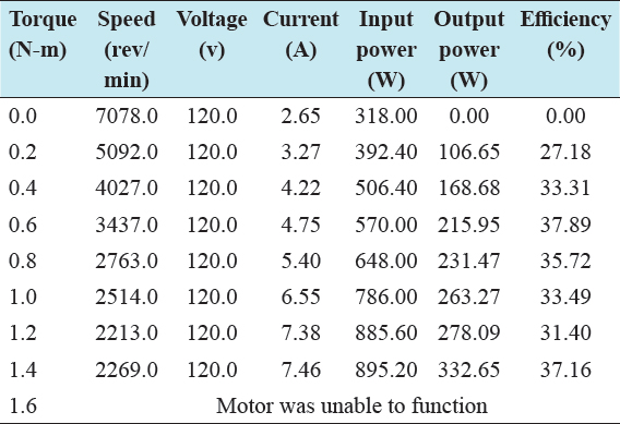
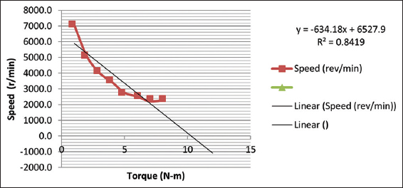
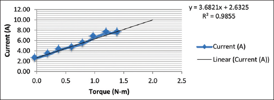
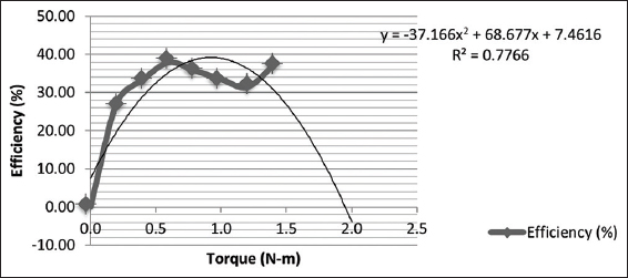
The aim of this paper is to investigate and compare the operating characteristics performance of a series universal motor (UM) when it is operating as an alternating current (AC) motor and as a direct current (DC) motor. The scope of the experiment was, therefore, limited to testing the series UM to study its behavior under each condition (AC and DC). The characteristics of the motor required to be investigated, under each of the test conditions, included speed, current drawn, and its efficiency in relation to various load setting. A laboratory experiment was carried out on an ETL174A model of series UM with a rated power of 0.25 kW by connecting the motor to an AC voltage source to carry out the AC test. Second, the motor was then connected to a DC supply to perform a DC test. In both cases, the load setting was adjusted so that the corresponding speed, current, and input power were measured. In addition, the output power and resultant efficiencies were determined through mathematical analysis. Results obtained were interpreted graphically to show the speed-torque, current-torque, and efficiency-torque characteristics for both the AC and DC test. The results further show that the operating characteristics of the ETL174A model series UM can operate both on AC and DC supply and that the behavior of the motor followed the same trends in each case, however, with differences in magnitudes of the quantities considered. Peak efficiency of approximately 42.7% and 37.9% was recorded when the UM ran under AC and DC supply, respectively. Furthermore, it was observed from the experiment that the speed (7080 rev/min) of the UM under DC no-load condition was far greater than the speed (5320 rev/min) under AC no-load condition. Conclusively, the deviation between results obtained during experiment and the expected results from literature did not alter the operating principle of the UM.

Keywords: Alternating current, direct current, experiment, load, universal motor

INTRODUCTION

Universal motors (UMs) are single-phase motors and are referred to as “universal” because they can operate from direct current (DC) and single-phase alternating current (AC) power sources.[1] In general, the UM is a motor designed in such a way that a DC machine is ran from an AC supply source.[2,3] UM runs up to dangerously high speed that is why they are built into the device they drive. UM can operate either single phase and AC or direct current (DC) at approximately the same speed as well as output (that is with similar characteristics) with ease.[2,4] This behavior is due to the fact that a DC motor will turn continuously in the same direction even if the armature and field currents are reversed at the same time. This is the exact behavior in an AC motor when connected to an AC source. UMs are also referred to as AC series motor and AC commutator motor. The torque angle is fixed by the brush position and it is normally at its optimum value of 90°.[5]

In general, if both rotor and stator mechanisms of a series connected motor are laminated properly, the resulting motor is referred to as a series UM. The laminated steel helps toward the reduction of core losses and Eddy current.[6]

UM has a very high starting torque due to the fact that it is series wound. Hence, it runs at dangerously high speed when it is not loaded on no-load condition. It also has a variable characteristic. UM is utilized in equipment where high-speed operation permits high horsepower per-unit motor size.[6] It finds application for both home and commercial devices due to its affordability in terms of cost and simplicity in regulation. For instance, in vacuum cleaners, the actual motor speed is equivalent to the load speed which is within 40,000 rev/min.[7] Another application where the UM speed is reduced is its application as the drink/food mixers by connecting it to a gear train. Others are portable drills, domestic sewing machine, motors controlling elevators, and crane lifts, among others.[1,7] UMs are basically of two types, the concentrated poles and non-compensated type characterized with low power rating and distributed-field compensated type characterized by high-power ratings.[4] Just like the DC series motor, the UM speed varies such that it exhibits both high speed when under-loaded and low speed when it is fully loaded.[4] However, the friction of the rotor and the windage load are factors that limit the speed on no-load. Studies have been carried out on UM over the years[1,8,9] to determine UMs performance, methodological approach, and review on its performance. For a giving UM, the armature current, ia flows through the series field and produces the d-axis flux, ɸd, Similarly, the ia also flows through the armature winding, producing the q-axis flux ɸq assuming that the Eddy current is neglected, both ɸd and ɸq are in phase with ia.[10]

According to Davidson et al.,[1] for DC excitation, the developed torque and induced voltage are, respectively, given as follows:

thumblarge

where, T = Torque developed by the motor, ɸd= Magnetic flux produced by series field Ia= Current flowing through the series field (armature current), ωm = Mechanical speed, Ea = The root mean square (rms) value of the back EMF.

In Figure 1, the series field UM is represented. The presence of a series field in the circuit model implies that they can also be referred to as series motor.[9]

thumblarge

Figure :1 Circuit representation of a series universal motor[9]

EXPERIMENTATION

The experiment was carried out using a series UM with model number ETL174A in the laboratory. The specification of the UM, as indicated on its name plate, is shown in Table 1. In Table 2, the equipment required for the DC and AC test and their corresponding ratings are presented.

Table :1 Technical specification of the universal motor (ETL174A model) tested

thumblarge

Table :2 Equipment required for AC and DC tests[11]

thumblarge

Procedure for AC Test

The motor under test was coupled to the dynamometer to measure the speed. The circuit was wired according to Figure 2 schematic.

thumblarge

Figure :2 Circuit connected to carry out the alternating current test on the motor

The motor was connected to an AC supply of 120 V. It was ensured that the supply voltage (120 v) was maintained throughout the test as indicated on the voltmeter connected to the circuit. The load setting was required to be varied from 0 Nm to 1 Nm with 0.2 increments. However, measurements could only be taken for three load setting – no load (0.0 Nm), 0.2 Nm, and 0.4 Nm, respectively, because the motor could no longer withstand higher values due to excessive vibrations, system overheating, and probably ageing. As a result, continuous tripping of the breaker was observed at this limit. However, values of obtained speed, supply current, and input power were measured and recorded. The power of the motor shaft was then calculated for each measurement taken using the Equation (4) below from Sen.[6]

thumblarge

Where, T is the torque in Nm and N is the speed in rev/min.

Furthermore, the efficiencies for each measurement were also determined

thumblarge

In Figure 3, the experimental setup for the AC test is presented.

thumblarge

Figure :3 Experimental setup for alternating current test

Procedure for DC Test

The same procedures carried out for the AC test, were also performed for the DC test using the circuit shown in Figure 4. Except that the supply voltage maintained this time, was 120 v DC. The motor load was required to be varied from 0 Nm up to 2 Nm in increments of 0.2 Nm but in actual sense, measurement could be taken for load settings from 0.0 Nm to 1.4 Nm for same reasons in the case of the AC test. Parameters recorded for this test included the speed and supply current only. In Figure 3, the experimental setup and measurements of variables are presented.

thumblarge

Figure :4 Direct current test circuit connection

Consequently, the values obtained were then used to calculate the input power using the formula:[6]

thumblarge

where

I = supply current, V = Supply voltage.

The output power and efficiency were also calculated for each load setting varied using Equations (4) and (5), respectively.

Furthermore, the efficiency, current, and speed characteristics of the DC UM were plotted with respect to the torques realized from the completed table.

RESULTS AND ANALYSIS

From Table 3, it was observed that the speed of the UM was at its peak (5320 r/min) when the motor was operating on no load with a zero (0%) efficiency. The efficiency was highest (47.72%) at the maximum torque of 0.4 Nm that the motor could withstand in the course of the experiment. The UM speed kept reducing for every increment in torque from that point forward. As observed from the experiment, this anomaly was due to the load impacted on the rotating shaft of the motor. Furthermore, the current and power (input) were seen to increase steadily for every increase of load setting.

Table :3 Results obtained for AC test carried out on the universal motor

thumblarge

From these values, the AC characteristics with respect to the various torque values in terms of the speed (r/min), current (A), and efficiency (%) were plotted. These are illustrated in Figures 5-7.

thumblarge

Figure :5 Alternating current characteristics of the motor in terms of speed-torque relation

thumblarge

Figure :6 Alternating current characteristics of the motor in terms of current-torque relation

thumblarge

Figure :7 Alternating current characteristics of the motor in terms of efficiency-torque relation

The speed curve illustrated in Figure 5 declines steadily with increase in load and resultant torque. From Figure 6, more current is drawn from the supply source for every increment in load. From the efficiency curve in Figure 7, the motor was seen to operate at a peak efficiency of 47.72%. In Table 4, the result obtained from the DC test is presented.

Table :4 Results obtained for direct current test performed on the universal motor

thumblarge

Comparing the results in Table 4 with that of Table 3, it could be seen that UM exhibits similar trends but differs with magnitude of the quantities under consideration. However, the maximum torque setting it operated was 1.4 N-m and just as in the case of the AC. Therefore, as the load increases, the torque also increased with resultant decrease in the speed. The fastest speed was 7080 r/min at no-load condition and its efficiency was zero (0%) too under same condition. The maximum efficiency computed was 37.89%. The supply voltage was kept steady at 120 v but the current kept increasing with every load increase (from 2.65 A to 7.46 A).

These results were used to plot DC characteristics curves with respect to the various torques in terms of the speed (r/min), current (A), and efficiency (%). These are illustrated in Figures 8-10.

thumblarge

Figure :8 Direct current characteristics of the motor in terms of speed-torque relation

thumblarge

Figure :9 Direct current characteristics of the motor in terms of current-torque relation

thumblarge

Figure :10 Direct current characteristics of the motor in terms of efficiency-torque relation

From the graphical analysis, it was observed that the UM operating this time as DC has almost the same characteristics as when it was operating as AC. The speed curve (illustrated in Figure 8) declines steadily with increase in load and resultant torque. From Figure 8, more current was drawn from the supply for every load increment. From the efficiency curve shown in Figure 10, the motor was seen to operate at a peak efficiency of 37.89% which was lower than that of the DC (47.72%).

Comparing these obtained results with results obtained in Tuncay et al.,[8] it was however observed that the readings were close but inconsistent. This could be attributed to overheating within the mechanical parts during operation, mechanical vibration, wear and tear, and environmental variations. Nevertheless, the practical behavior in all cases followed same trends when compared with Tuncay et al.[8] Furthermore, as observed in Figures 5-10, a high R-squared value for each of plot was obtained using the Excel software and this defines the predicted power of the model and the experiment in general. For instance, in Figure 6, it can be said that R-squared percent (95.49%) of the variability in speed in rev/min can be explained by the model (variability in torque).

CONCLUSIONS

In this study, the operating characteristics of the series UM were investigated under DC and AC test using experimental analysis to show that how it operates both on AC and DC supply. Quantities investigated on the UM mainly included torque of motor, speed, current, and efficiency for both the AC and DC operations. The results from the experiment showed that the behavior of the motor followed the same trends in each case. However, there were differences in magnitudes of the quantities considered. Furthermore, the deviation between results obtained during experiment and the expected results did not alter the operating principle of the UM.

REFERENCES

1.  Davidson I, Lamola J, Xia X, Gitau MN. Design and Performance Analysis of a Universal Motor for Industrial Alarm Systems. Cape Town, South Africa:10th Southern African Universities Power Engineering Conference;2001. 9-12.

2.  Fitzgerald AE, Kingsley C, Umans SD. Electric Machinery. 6th ed. New York:McGraw-Hill Company Inc.;2003. 395-6.

3.  Chapman SJ. Electric Machinery Fundamentals. 4th ed. New York:McGraw-Hill Company Inc.;2005. 634.

4.  Theraja BL, Theraja AK. A Textbook of Electrical Technology. 23rd ed. New Delhi:S. Chand and Company Private Ltd.;2002. 1292-4.

5.  Petruzella FD. Electric Motors and Control Systems. 1st ed. New York:McGraw-Hill Company Inc.;2010. 113-4.

6.  Sen PC. Principles of Electric Machines and Power Electronics. 3rd ed. United States:John Wiley and Sons Inc.;2013. 362.

7.  Di Gerlando A, Perini R. Modelling and Test Validation of High Speed Universal Motors Fed Via a Triac. San Antonio, TX:IEEE International Conference on Electric Machines and Drives;2005. 1173-8.

8.  Tuncay RN, Yilmaz M, Onculoglu C. The Design Methodology to Develop New-Generation Universal-Motors for Vacuum Cleaners. IEMDC 2001. Cambridge, MA:IEEE International Electric Machines and Drives Conference;2001. 926-30.

9.  Shrivastava K, Pawar MD. A review on types of DC motors and the necessity of starter for its speed regulation. Int J Adv Res Comput Commun Eng 2016;5:61-3.

10.  Available from:https://www.groschopp.com/video/choose-electric-motor-universal-motors. [Last accessed on 2019 Nov 27].

11.  Sedghi K. An Electrical Machines and Energy Conversion Laboratory Manual. 2nd ed. United States:California State University;2010. 1-45.